Geometry
Define the exterior boundary of the section and the boundaries between materials, import them from DXF, and use parameters.
The geometry of a model is a cross-section of the slope: an exterior boundary around the whole section and interior boundaries that divide it into material regions.
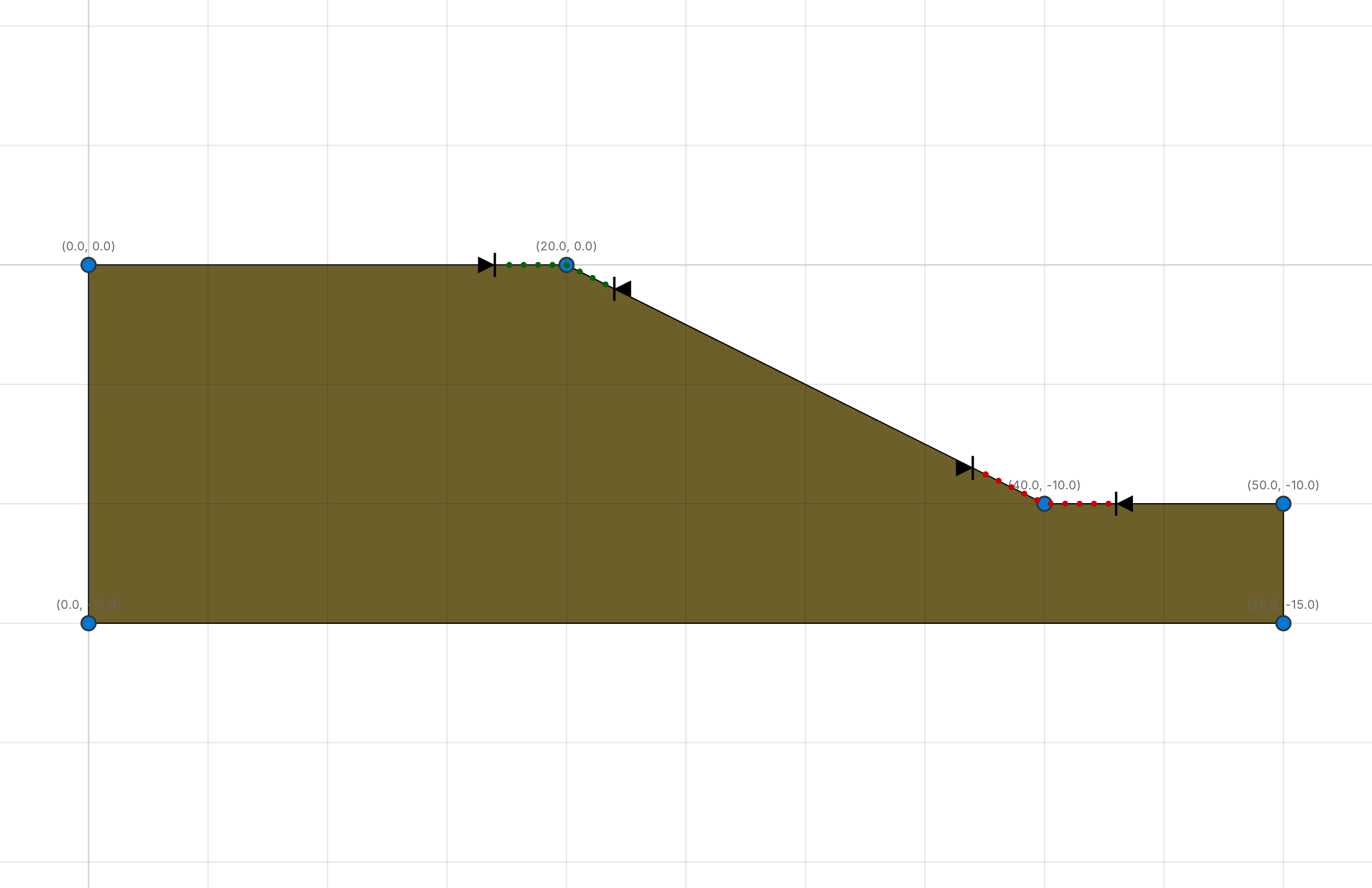
Exterior boundary
Open Model › Boundaries › Exterior. The window lists the points of the boundary in order, with their X and Y coordinates in metres.
- Type new coordinates in the table, or drag a point on the canvas.
- + Add Point adds a point 5 m to the right of the last one.
- The button at the end of a row removes the point. The boundary keeps at least three points.
On the canvas you can also right-click an edge and choose Add Point, or right-click a point and choose Delete Point. Delete removes the selected point.
The top of the exterior boundary is the ground surface. Slip surfaces enter and leave the slope there.
Interior boundaries
Open Model › Boundaries › Interior. Interior boundaries divide the section into regions, one material each. A boundary can be:
- an open polyline from one side of the section to the other, for a layer boundary, or
- a closed polygon (the last point equal to the first), for a lens.
Add creates a horizontal boundary across the model at mid-height; Delete removes the selected one. Select a boundary in the list to edit its points in the table below, or click it on the canvas.
When you drag a point near a point of another line, it snaps to that point, so that boundaries meet exactly.
Regions and materials
cSlope finds the regions between the boundaries automatically. Open Model › Materials › Assign to give each region a material: the window lists the regions with a material for each. You can also click a region on the canvas and choose its material from the menu. A region without an assignment uses the first material in the list.
Define the materials themselves in Model › Materials › Define. See Materials.
Snapping and coordinates
The status bar has a Snap checkbox and a grid size from 0.1 m to 5 m. With Snap on, dragged points snap to the grid. Points always snap to points of other lines nearby. The status bar shows the cursor position in model coordinates.
Import from DXF
File › Import DXF reads a section from a CAD drawing and adds it to the project as a new model, named after the file.
- The closed polyline with the largest area becomes the exterior boundary. The drawing must contain one.
- Open polylines on a water layer become piezometric lines: a layer whose name contains water, piezo, vatten or grundvatten, or the word gw or wt.
- All other polylines and lines become interior boundaries. Lines on the same layer are joined end to end.
The drawing must be an ASCII DXF. Polylines (LWPOLYLINE, POLYLINE) and lines (LINE) are read; arcs, splines and blocks are skipped, and the import message lists what was skipped. Drawing units (mm, cm, m, inches, feet) are converted to metres.
After the import, assign materials to the regions, add the materials' properties and set the search limits before running the analysis.
Tip
Draw the outline of the slope as one closed polyline, and each layer boundary as one polyline that reaches the outline at both ends.
Parameters
Parameters are named values that you can use instead of numbers. Open Model › Parameters › Define and add parameters with a name and a value. A value can be a number or an expression.
Expressions can use numbers, parameter names, +, -, *, / and parentheses. For example, with the parameters H = 10 and slope = 2, the toe of a slope can be at X = H * slope.
Parameters can be used in:
- the coordinates of the exterior and interior boundaries and of the piezometric lines,
- the properties of the materials,
- the magnitude and position of distributed and line loads.
Change a parameter and everything that uses it changes with it. Parameters are also the easiest way to run a sensitivity analysis of a dimension. A point coordinate given by a parameter does not move when you drag the point on the canvas.