Reinforcement and piles
Anchors, grouted tiebacks, soil nails, geosynthetics, pile rows and sheet pile walls, and how their forces enter the analysis.
Open Model › Support › Reinforcement. The window has two tables: reinforcement (elements that act in tension) and piles and sheet piles (elements that act in shear).
The forces of an element are per element. cSlope divides them by the out-of-plane spacing S to get the force per metre run of the slope. For a geosynthetic sheet that covers the whole slope, use S = 1.
Reinforcement
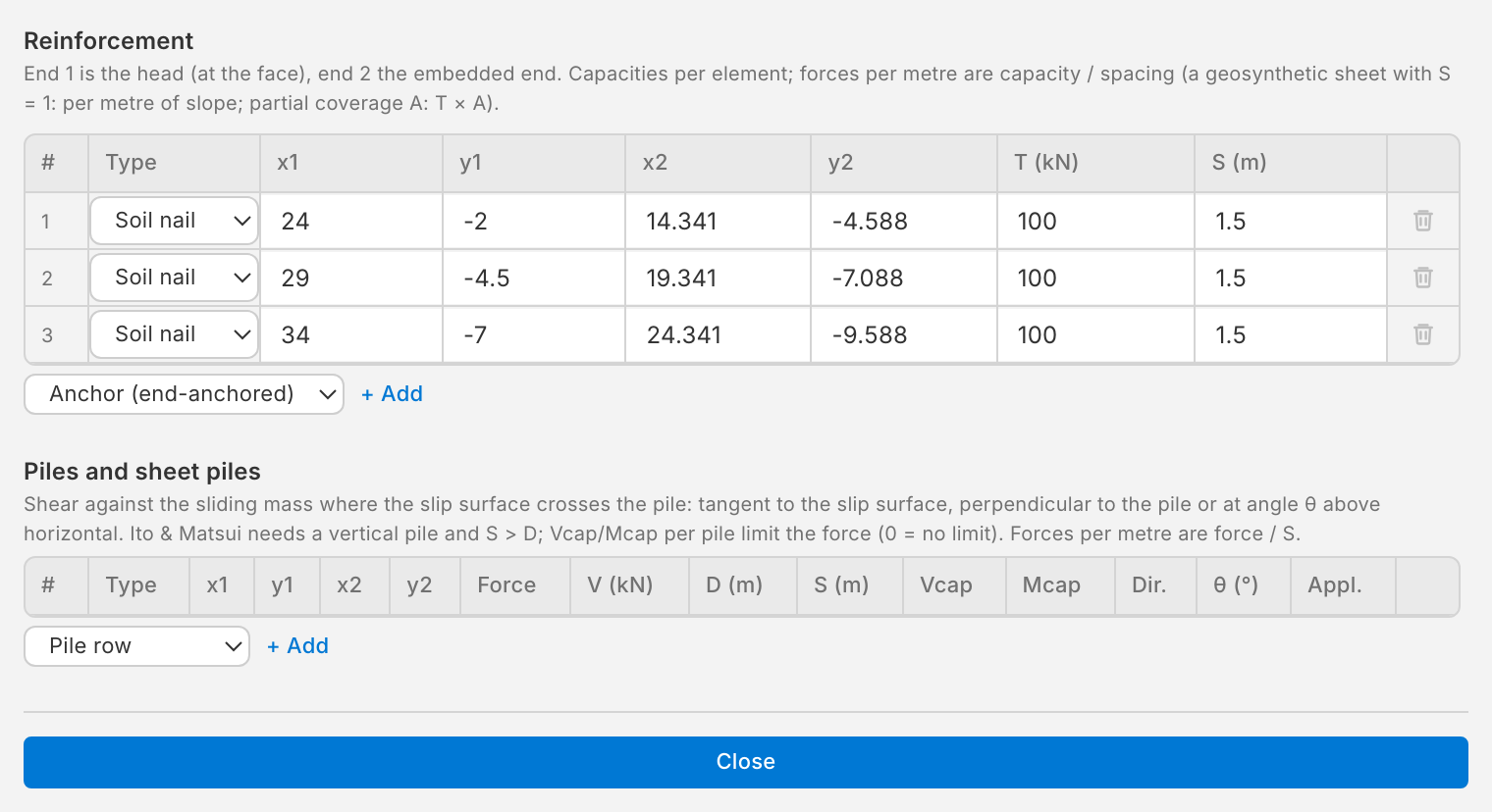
Each row is one element, from end 1 (the head, at the face) to end 2 (the embedded end), with the coordinates x1, y1, x2, y2. Choose a type in the list below the table and click + Add. A new element is 10 m long and starts 1 m below the ground at the middle of the model, inclined 15° downwards into the slope (geosynthetics horizontal).
| Type | T (kN) | S (m) | Pullout | Force direction | Application |
|---|---|---|---|---|---|
| Anchor (end-anchored) | 200 | 2 | None, ends fully anchored | Along the element | Active |
| Grouted tieback | 300 | 2 | Bond, 60 kN/m over a 5 m bonded length | Along the element | Active |
| Soil nail | 100 | 1.5 | Bond, 15 kN/m over the whole length | Along the element | Passive |
| Geosynthetic | 50 | 1 | Interface friction, δ = 20° | Tangent to the slip surface | Passive |
These are starting values: changing the type of an element applies the new type's values and keeps the geometry. Edit them to match the design.
T is the tensile capacity of the element. Click a row to see and edit the element's other properties:
Pullout
Where the slip surface crosses the element, the force it can carry is the smallest of its tensile capacity and its pullout resistance on either side of the crossing.
- None — ends fully anchored: the element is held at both ends; only T limits the force.
- Bond strength along the element: a pullout resistance per metre of element, Bond strength (kN/m), acting over the Bonded length at end 2 (0 means the whole element, as for a soil nail).
- Interface friction (overburden): for a geosynthetic, the resistance per metre is , with the Adhesion a, the Interface friction δ and the vertical effective stress at the element.
With pullout, Plate / connection at end 1 and Anchorage at end 2 limit the force that the ends can take.
Force direction
- Along the element: the force acts in the direction of the element, as for a stiff bar.
- Tangent to the slip surface: the force acts along the slip surface, as for a flexible element such as a geosynthetic.
- Bisector of the two: halfway between.
Application
- Active (not divided by F): the force is a known, allowable force, such as a prestressed anchor. It is applied as it is.
- Passive (divided by F): the force is an ultimate capacity that is mobilised together with the soil strength. Like the soil strength it is divided by the factor of safety.
Piles and sheet piles
A pile row or a sheet pile wall resists the sliding mass in shear where the slip surface crosses it. Choose Pile row or Sheet pile wall below the table and click + Add. A new pile is vertical and 10 m long, from the ground at the middle of the model.
| Column | Meaning |
|---|---|
| Force | Given: you enter the shear force V. Ito & Matsui: the force is computed from the soil flowing between the piles. |
| V (kN) | The shear force per pile (Given). |
| D (m), S (m) | Pile diameter and spacing. |
| Vcap, Mcap | The shear and bending capacity per pile, which limit the force. 0 means no limit. |
| Dir. | The direction of the force: tangent to the slip surface, perpendicular to the pile, or at an angle θ above the horizontal. |
| Appl. | Active, or passive (divided by F). |
The Pile row starts with Ito & Matsui, D = 0.6 m and S = 2 m, tangent and passive. The Sheet pile wall starts with a given force of 100 kN, S = 1 m, active and horizontal.
The Ito & Matsui method needs a vertical pile and a spacing larger than the diameter. The window warns when a pile does not meet these conditions; give the force of such a pile directly.
Lime-cement columns
Lime-cement columns are modelled as a material, not as a support element. See Materials.
On the canvas and in the results
Reinforcement and piles are drawn on the canvas and on the result sheet, with the force that each element carries on the critical surface. They are positioned through the tables; they cannot be dragged on the canvas.
With partial factors on, the factors apply to the soil strength and the loads. The Ito & Matsui pile force is computed from the factored soil strength; all other capacities are used as entered, so enter them as design values.